ESPHome Temperature Controlled Fan v2 - The Deluxe Edition!
One of the first videos I made for my YouTube channel walked you through creating a temperature-controlled fan using ESPHome. Since then, I thought I could do better, so I’ve made a number of improvements and come up with a super-deluxe version of my USB fan controller.
If you haven’t seen the first video then you should check it out. So why am I creating a better version then? Well, let’s start with the hardware: the original version was just bodged together and stuck inside an old battery case with a USB cable sticking out of it and the transistor protected by insulation tape. It wasn’t very pretty. This time I decided to stick all of the components on a bread board, soldering them all in place.
Shopping List
- USB Fan
- Prototyping Breadboard
- D1 Mini
- 5mm Common Cathode RGB LED
- S8050 NPN Transistor
- USB A Socket
- BMP280 Sensor
- Project Enclosure
- Solid Core Hookup Wire
- Header Pins
Hardware Build
I chose a D1 Mini this time with an ESP8266 chipset instead of the ESP32 I used before. The D1 Mini is a bit cheaper, smaller, and has just about enough connection points for this project.
Instead of a USB cable, I used an actual USB socket and soldered it to the bread board. The temperature sensor is the same, although I used a BME280 instead of a BMP280 - you can use whichever one you manage to get hold of, just remember to change the letter in the configuration later.
I also decided to fit an RGB LED - the one I used is a 5mm common cathode LED, and I can use that to display status alerts. Once all of the components are on the board, I needed to connect them all up. This is the wiring diagram for this project:
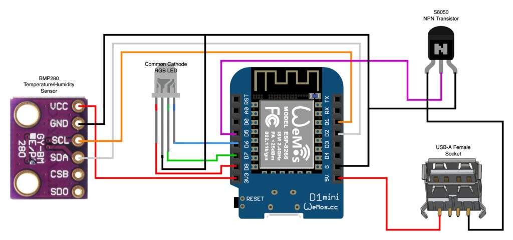
One thing to point out here is that all of those black wires are terminating on the ground pin of the D1 mini. From a diagram perspective this is perfectly fine, but in real life having all of those cables soldered to the same pin is a nightmare. I soldered a separate header pin to the breadboard away from the microcontroller, just to give me plenty of space to solder all of the wires to it.
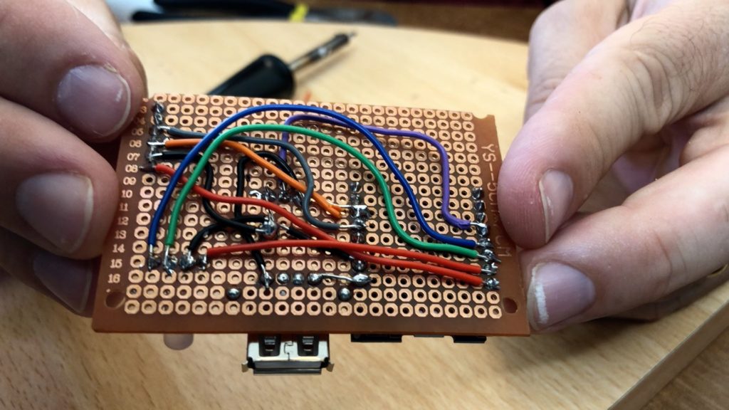
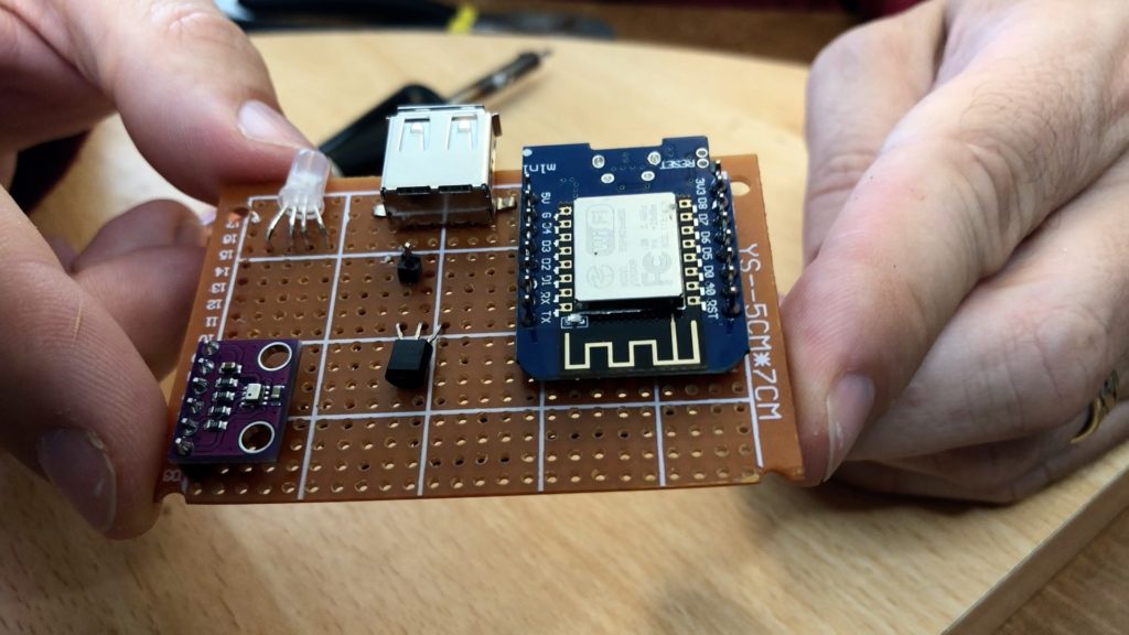
And here’s the finished product showing you the top with the components and the underside with all of the wires. I think it’s a lot neater than the original version already. The eagle-eyed amongst you might notice that these photos don't match the actual finished product you'll see later on - super secret behind the scenes gossip: I fried the D1 Mini on my first attempt at assembling this and had to start again! In my second attempt I moved the USB port back a bit further onto the board so as it doesn't stick out so much, and moved the transistor closer to the USB port's pins to make the wiring a bit easier.
The Software
And now to the software. The biggest issue with the original version was its reliance on Home Assistant. If your wifi went down, or Home Assistant went down, then the fan would stop running because all of the logic was in Home Assistant. Well this deluxe version moves all of that fan control logic inside the microcontroller. It’ll run totally autonomously even if it loses its network connection.
substitutions:
  device_name: it-cabinet-fan
  friendly_name: "it-cabinet-fan"
  device_description: "IT Cabinet Fan"
  temperature_threshold_top: "30" # At what temperatere, in celcius, should the fan turn on?
  temperature_threshold_bottom: "29" # At what temperature, in celcius, should the fan turn off?

esphome:
  name: '${device_name}'
  comment: '${device_description}'

esp8266:
  board: d1_mini

# Enable logging
logger:

# Enable Home Assistant API
api:

wifi:
  ssid: !secret wifi_ssid
  password: !secret wifi_password

  # Enable fallback hotspot (captive portal) in case wifi connection fails
  ap:
    ssid: '${device_name}'
    password: !secret fallback_password

captive_portal:

ota:
  - platform: esphome

safe_mode:
  disabled: false
  reboot_timeout: 10min
  num_attempts: 5

# Defines the pins for the temperature sensor
i2c:
  sda: 04
  scl: 05
  scan: true
  id: bus_a

# Output components for LED pins
output:
  - platform: esp8266_pwm
    id: output_red
    pin: D8
  - platform: esp8266_pwm
    id: output_green
    pin: D7
  - platform: esp8266_pwm
    id: output_blue
    pin: D6

# BME/BMP280 temperature sensor
# Controls the state of the fan switch based on the temperature readings
sensor:
  - platform: bme280_i2c
    address: 0x76
    temperature:
      name: "${device_description} Temperature"
      id: it_cabinet_temperature
      on_value_range:
        - below: '${temperature_threshold_bottom}'
          then:
            - switch.turn_off: switch_fan
        - above: '${temperature_threshold_top}'
          then:
            - switch.turn_on: switch_fan

#.A GPIO switch to control the power to the USB port, into which the fan is plugged
switch:
  - platform: gpio
    pin: D5
    name: "Fan Switch"
    restore_mode: ALWAYS_OFF
    id: switch_fan
    internal: true

# Publish a binary sensor to Home Assistant that mirrors the fan switch state
# We don't publish the actual switch because it is purely controlled internally by ESPHome
binary_sensor:
  - platform: template
    device_class: "heat"
    name: '${device_description}'
    lambda: |-
      if (id(switch_fan).state) {
        // Switch is on, mirror this here
        return true;
      }
      else {
        return false;
      }

# A status LED
light:
  - platform: rgb
    name: "Status LED"
    id: status_led
    red: output_red
    green: output_green
    blue: output_blue
    internal: true


interval:
  # Every 3 seconds, if the fan is off, then flash the LED green
  - interval: 3sec
    then:
      - if:
          condition:
            switch.is_off: switch_fan
          then:
            - light.turn_on:
                id: status_led
                transition_length: 1s
                red: 0.0
                green: 1.0
                blue: 0.0
                brightness: 0.7
            - delay: 1000ms
            - light.turn_off:
                id: status_led
                transition_length: 1s
          else:
            - light.turn_on:
                id: status_led
                transition_length: 0.1s
                red: 1.0
                green: 0.0
                blue: 0.0
                brightness: 0.7
Now this fan is going in the IT cabinet in my garage, so it’s called IT cabinet fan. At the top of the config I’ve defined a couple of parameters - you can tweak any of these, the description and the names you should customise as you see fit. The two temperature thresholds should be changed to meet your requirements. The top value defines the temperature at which the fan will turn on, and the bottom value defines when it will turn off. You’ll probably want them close, but not the same.
If you’re using my wiring diagram then you shouldn’t need to change anything else, but just to quickly run you through the rest of the config, the 'i2c' section defines the pins used by the temperature sensor. and the 'output' section defines the pins used by the LED.
The temperature sensor section is the clever part. Note that the platform says bme280 for me, but if you get a bmp280 instead then change that here. There’s an action associated with the temperature sensor (on_value_range) that executes when the sensor value rises above the top threshold or drops below the bottom threshold. It turns the fan switch object on or off the as appropriate.
That switch object is the next thing to be defined, and is a GPIO switch using pin D5. Note that this switch is declared as internal which means that Home Assistant can’t see it. That’s because we don’t want it to be controlled manually - instead we define a binary sensor a few lines later. This binary sensor essentially mirrors the status of the fan, so Home Assistant sees this binary sensor instead of the switch, and you can view its status but not control it.
Lastly we have the RGB LED, this section sets up the light entity and makes sure that it’s internal only, then this interval section runs every 3 seconds. It checks to see if the fan switch is off, and if so it slowly pulses the LED green. This is just intended as a kind of confirmation of standby. If however the fan switch is on, it sets the LED to solid red. This status LED could be quite useful for testing without a fan connected because it should tell you what the USB port’s status is.
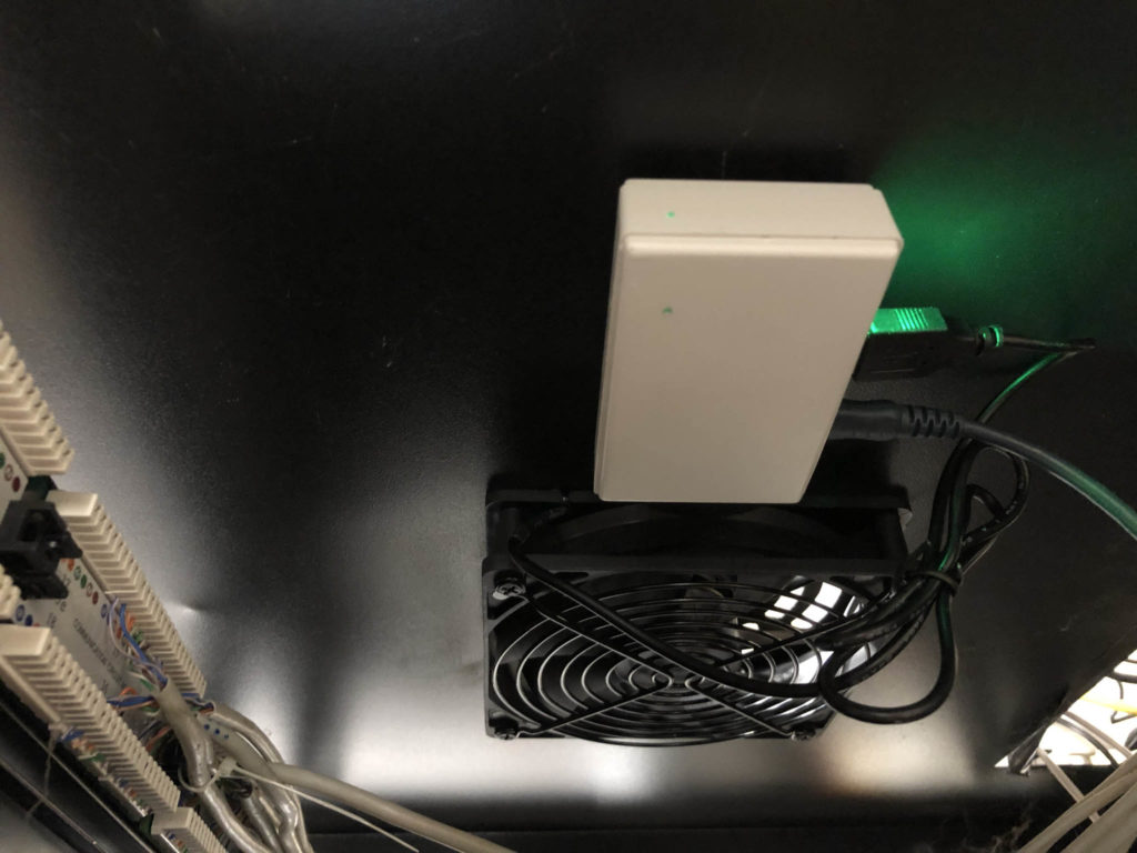
Once configured it’s time to test it. Connect it all together with your chosen USB Fan - this time I’m using a 120mm Eluteng USB fan. Now to test it, you need a way to apply controlled heat to the temperature sensor. I found that the best way to test it is with a travel hairdryer.
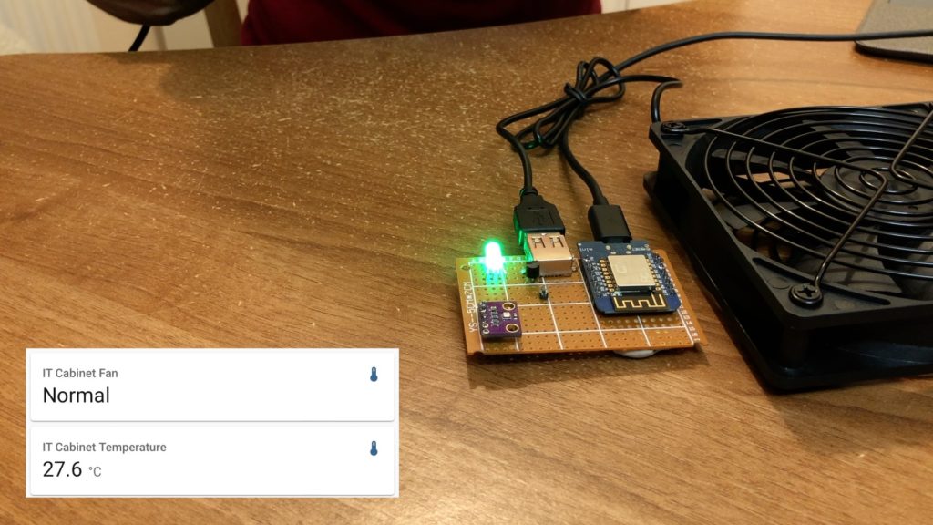
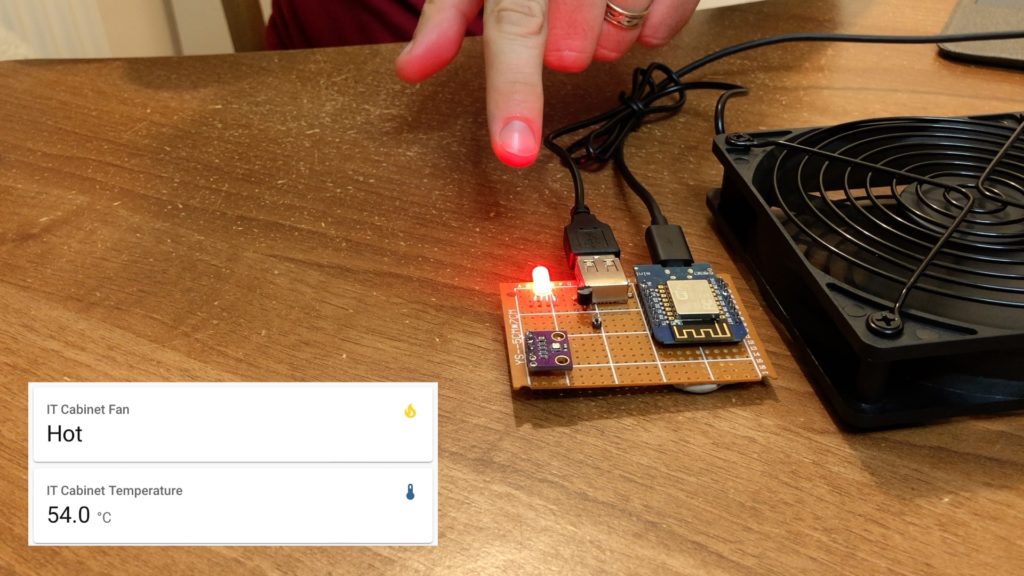
When the fan is off and the temperature sensor is below the threshold the fan is off, but if I apply a bit of heat it turns on.
There is one final task - this project needs a case. Now I know I’ve left this to last, but I had of course planned the layout and size from the start. Make sure you have a suitably sized project enclosure and cut your breadboard to size before you start.
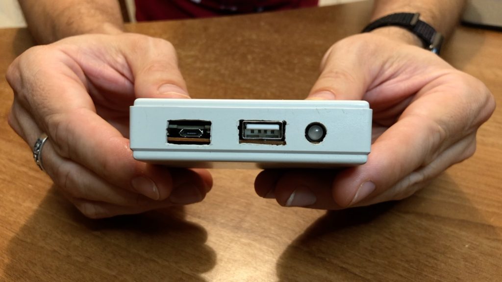
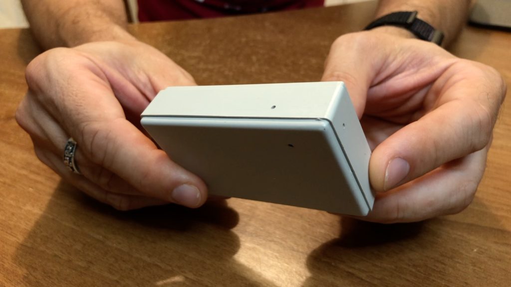
I’ve cut out a hole for the micro-USB power, another for the USB port for the fan, and I drilled a hole for the LED. Notice that I’ve also drilled a few smaller holes around by the temperature sensor to allow a bit of airflow which will hopefully give me a more accurate reading.
I hope you enjoyed seeing this little project, I know there’s more soldering and effort than the previous version but I think you’ll agree that this is a much neater solution and generally improved all round.