
Temperature Controlled Cooling Fan using ESPHome

I have a real dislike of cables being visible around the home, so when we last decorated our living room about five years ago I took the opportunity at the time to hide as much of our AV kit as possible. The Apple TV, amplifier, Xbox, and all the various cables connecting it all together, went inside a cabinet. My wife chose a nice spacious wooden cabinet, and I cut some massive holes in the back of it so as all of those cables could easily run to the kit inside/ I even got a (now discontinued) Logitech Harmony Elite remote which came with a couple of IR blasters so as it could all be controlled without the need to have the cupboard doors open.
I was very pleased with myself, and it looked a lot tidier. But, there was one major problem - it got seriously warm inside that cupboard. I had an old original Raspberry Pi lying around so I rigged up a temperature sensor and a USB fan to the Raspberry Pi’s GPIO connectors, and using a python script on the Pi I bodged together what was in effect a thermostatically controlled fan. As the cupboard heats up, the fan comes on to help vent that heat out, and as the temperature starts to drop again the fan turns off. This was working great until about a month ago. The SD card in the Raspberry Pi died and went to that special place that all overused SD cards eventually go, and my fan controller was no more.
But this gave me an opportunity to re-geek the solution! I use Home Assistant as my home automation solution, and there’s an amazing add-on for Home Assistant called ESPHome. This add-on is designed to help you make and use your very own Internet of Things devices. You can create WiFi connected sensors for things like temperature, air quality, distance , energy monitoring, you name it. You can also connect actuators like lights, relays for switches, and in my case, a fan. Most ESPHome projects aren’t for beginners because they inevitably end up needing a soldering iron. But, with a bit of careful planning and shopping around, you can get all the components you need with pre-soldered headers and use what are called Dupont cables to connect them all together. ESPHome provides all of the services needed to get your sensors and actuators talking over your Wifi network back to Home Assistant. You create a little YAML file defining things like the type of ESP microcontroller you have, your Wifi network details, and crucially the details of the sensors and actuators attached to your microcontroller.
I already had an AC Infinity USB fan bolted to the back of my AV cabinet, and a BMP280 temperature sensor. I had to order an ESP32 microcontroller. I chose the ESP32-Wroom-32D because while looking around at other people’s projects this particular board was mentioned a number of times. There’s also the D1 mini that gets a lot of love too and I have one of those in use for another project.
Here's a complete list of components required to create this project:
- ESP32-Wroom-32D: https://amzn.to/3uzWX7q
- S8050 NPN Transistor: https://amzn.to/3uxss1J
- Dupont Wires: https://amzn.to/37G2pfZ
- USB A Header Cable: https://amzn.to/3E3fKuG
- BMP280: https://amzn.to/3KCECvN
- AC Infinity USB Fan: https://amzn.to/37Ghlud
And most importantly here's the wiring diagram:
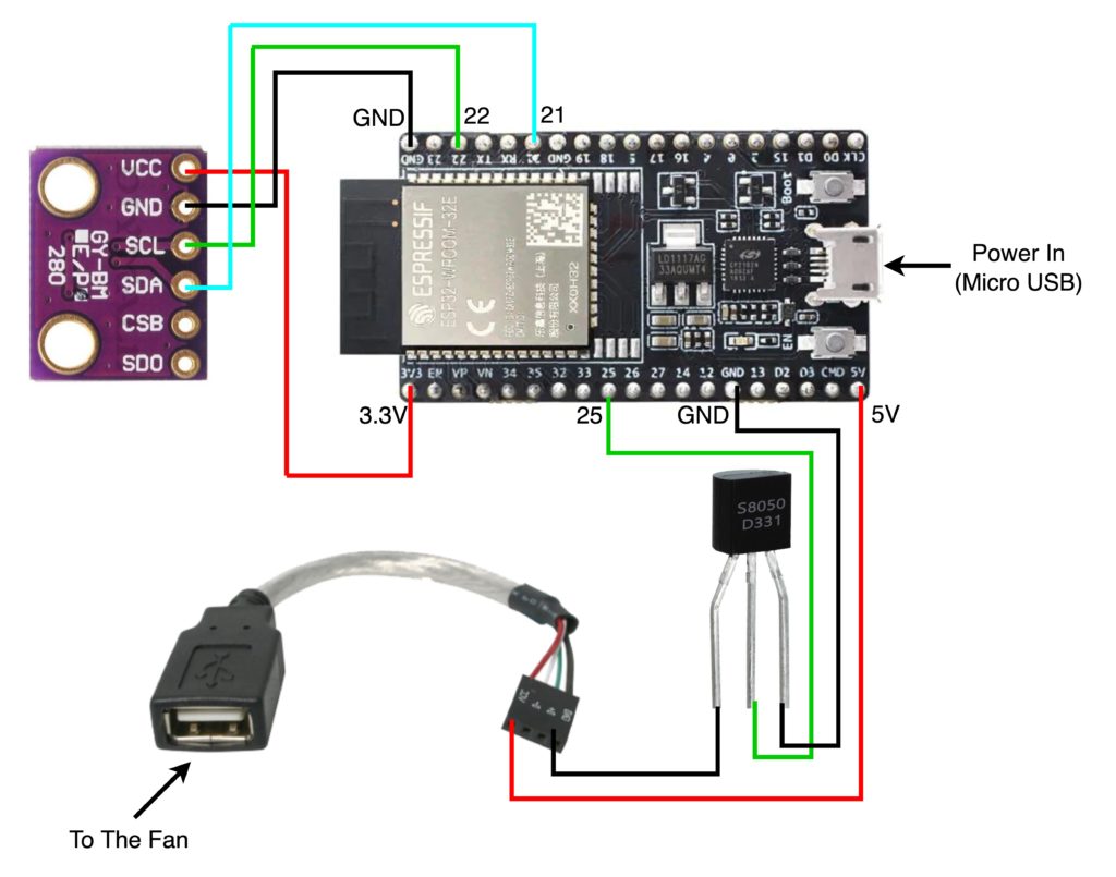
First things first, you can’t just connect your USB fan straight to your microcontroller. You need to stick a little NPN transistor on the ground wire first. I soldered mine in place to make it nice and compact, but you can just use dupont cables and lots of electrical insulation tape. For the temperature sensor, in addition to 3.3v power and ground, you also have two data terminals called SCL and SDA.
Once it was all wired up, you need to programme it. I found the easiest way to do this was to physically plug it into the Raspberry Pi running Home Assistant. I could then use the ESPHome interface in Home Assistant to Install directly. You can apparently plug it into your computer and using some sort of magic remote browser-based serial connection you can install it that way, but I just couldn’t get it to work - that might be because I’m using a Mac, you might have better luck if you’re using Windows. Once you’ve configured it the first time, any further changes to the configuration can all be done wirelessly. Here's the YAML configuration file I used to create my sensor:
substitutions:
  device_name: av-cabinet-fan
  friendly_name: "av-cabinet-fan"
  device_description: "AV Cabinet Fan and Temperature Sensor"

esphome:
  name: '${device_name}'
  comment: '${device_description}'

esp32:
  board: nodemcu-32s

# Enable logging
logger:

# Enable Home Assistant API
api:

wifi:
  ssid: !secret wifi_ssid
  password: !secret wifi_password

  # Enable fallback hotspot (captive portal) in case wifi connection fails
  ap:
    ssid: '${device_name}'
    password: !secret fallback_password

captive_portal:

ota:
  - platform: esphome

safe_mode:
  disabled: false
  reboot_timeout: 10min
  num_attempts: 5

web_server:
  port: 80
  auth:
    username: !secret esphome_web_username
    password: !secret esphome_web_password

i2c:
  - id: bus_a
    sda: 21
    scl: 22
    scan: true

sensor:
  - platform: bmp280_i2c
    i2c_id: bus_a
    address: 0x76
    temperature:
      name: "AV Cabinet Temperature"
      id: av_cabinet_temperature

switch:
  - platform: gpio
    pin: 25
    name: "AV Cabinet Fan"
    restore_mode: ALWAYS_OFF
For those of you new to ESPHome, take a note of the lines with '!secret' in them. It's best practise to edit the 'secrets.yaml' (in the ESPHome web interface, click on the 'Secrets' button in the top-right) and add entries for things like wifi_ssid and wifi_password. This not only helps keep your individual device configuration files clean of your secret data, but it also makes it a lot easier to update your passwords on all devices if it's just kept in one place. You can of course replace the whole of '!secret wifi_ssid' with your actual SSID if you want to, and the same with the other !secret lines.
Let’s jump to the point at which it was actually working! I found an old unused plastic battery case in the garage, so I cut a few holes in it and managed to cram all of the components inside. I made sure that the temperature sensor was sticking out of the top, just to help it get a more accurate reading. Once in place inside the cupboard, I gave it a quick test by toggling the automatically created switch entity in Home Assistant, and then confirmed that the temperature sensor was indeed sending data.
Finally… that fan needs automating. This one is very simple, if the temperature drops below 28.5 degrees Celsius then the fan turns off, if it rises above 32 degrees then the fan turns on. There’s a bit of a gap between the two values in order to stop frequent toggling of the fan switch when the temperature is hovering around a particular level, and I figured out those thresholds by keeping an eye on the temperature graph for a few days.
alias: TV Fan
description: ''
trigger:
  - platform: state
    entity_id: sensor.av_cabinet_temperature
condition: []
action:
  - choose:
      - conditions:
          - condition: numeric_state
            entity_id: sensor.av_cabinet_temperature
            below: '28.5'
          - condition: state
            entity_id: switch.av_cabinet_fan
            state: 'on'
        sequence:
          - service: switch.turn_off
            target:
              entity_id: switch.av_cabinet_fan
            data: {}
      - conditions:
          - condition: numeric_state
            entity_id: sensor.av_cabinet_temperature
            above: '32.0'
          - condition: state
            entity_id: switch.av_cabinet_fan
            state: 'off'
        sequence:
          - service: switch.turn_on
            target:
              entity_id: switch.av_cabinet_fan
            data: {}
    default: []
mode: single
ESPHome is really fun to play with, and it is very satisfying when you manage to get something working like this. But, it’s also quite frustrating and can be a steep learning curve so be warned, if you go down this rabbit hole you’re likely to lose days of your life to it.