
ESPHome Fan v3: Variable Speed (PWM) and Temperature Control
I know, I seem to have a bit of an obsession with connecting fans to ESPHome. This is my third article on the subject! But this time it’s by special request and I’ve put together a little project that lets you control the speed of the fan, and also uses a temperature sensor to set that speed.
Shopping List
- Arctic P12 PWM Fan: https://amzn.to/3UvafvB
- BMP280 temperature sensor: https://amzn.to/3ukayyL
- KY-019 Relay: https://amzn.to/3iBVQjJ
- D1 Mini: https://amzn.to/3umCKkr
- 12v-5v Converter: https://amzn.to/3Fkz60F
- 12v Power Supply: https://amzn.to/3Vz9anJ
- Dupont Cables: https://amzn.to/3UuC6vZ
Overview
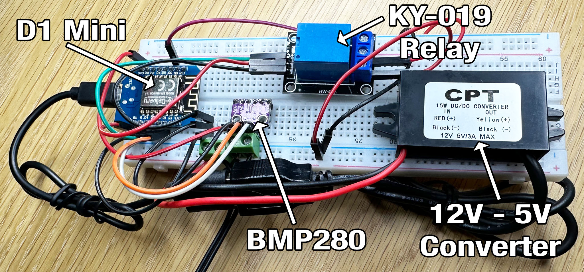
Don’t worry, this is not as scary as it looks. It’s just laid out bare on this breadboard so as you can easily see what’s happening.
Let’s start with the power supply. I’m running this project using a 12v power adapter - I’ve cut off the barrel connector so as I can screw the cables into the green terminals near the bottom - make sure you note which wire is positive and which is negative! Usually the wire with markings on is positive but make sure you know using a multimeter, or sometimes there’s a diagram on the power supply’s label. The reason for using a 12v power supply is because most popular fans tend to run at 12v.
This big black module is a voltage converter. It takes the 12v input and drops it down to 5v. There are lots of different variations of this module out there, but this specific one actually gives me two USB ports which is very convenient for plugging in the D1 mini.
The D1 Mini is of course the brains of the operation and is going to be our link between these various components and Home Assistant.
The module with a blue box on its back is a relay. This is needed because a 12v PWM fan can’t actually be stopped just by controlling the PWM signal. Even at the slowest setting the fan will still be turning. So... we use the relay to toggle the power to the fan.
Lastly there’s the little red module which is a BMP280 temperature sensor. I suggest you buy a few of these because in my experience they have a high failure rate 🙁
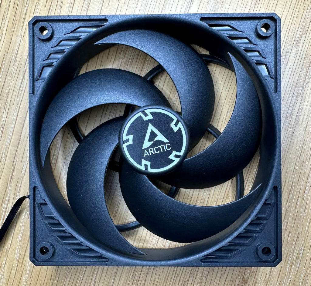
In addition to these control components, you'll of course need a fan. I've chosen a 12v fan made by Arctic. Specifically this is the PWM version, or Pulse Width Modulation. That means it has a 4-pin connector which is important because it’s that 4th pin that allows you to signal to the fan how fast you’d like it to spin.
Wiring Diagram
I know it looks like a lot of tangled wires there but there is a method to the madness and I’ll show you on the wiring diagram.
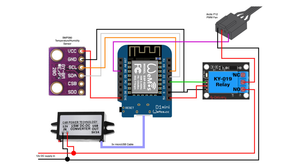
The 12v power supply comes in at the bottom and is split off firstly into the voltage converter to power the D1 Mini, and secondly to the relay and fan. The 12v positive terminates in the NO (Normally Open) connector on the relay, and then continues up to the positive input of the fan which is pin 2. The ground is just a straight connection from the input ground to pin 1 on the fan. This allows the relay to physically switch the 12v power to the fan, breaking the circuit by default meaning that the fan is truly off.
The relay itself is powered by the 5v output from the D1 mini, but the important connection here is the green wire running to pin D3. This is where the microcontroller will send the signal to the relay to tell it to switch on or off. To control the speed of the fan, we also need to send a PWM signal. This purple wire connects from pin D0 on the microcontroller to pin 4 of the fan.
And lastly then we have the BMP280 module which uses the I2C connection on the microcontroller. I’m using the module’s default pins of D1 and D2 for SCL and SDA communication, and of course the module itself needs a 3.3v power supply which is taken from the D1 Mini too.
I just want to make a point about the voltage converter I've used in this project because it’s quite clearly a big bulky component. This one is designed for use in cars to give you some hard wired USB ports. You could instead go with what’s called a buck converter which are much smaller and cheaper, but quite often need you to manually tune the output voltage using a screwdriver and a multimeter, and then they often need a heatsink to stop them melting. I’ve chosen this pre-built sealed module instead because it’s a lot easier for beginners to use, but if you know what you’re doing and want to make this more compact then use a buck converter.
Anyway once you’ve connected it all together you’ll need to program the D1 Mini. I suggest you remove the D1 Mini from the project and plug it directly into your PC using USB for this part, and then you can connect it back into the rest of the project after you’ve done the initial flashing, just in case you’ve accidentally cross-wired something you don’t want to push 12v back down your computer’s USB port.
Configuration
substitutions:
  device_name: fan-speed-controlled
  friendly_name: "fan-speed-controlled"
  device_description: "Fan with speed control"
  temperature_threshold_low: "20" # At what temperature, in celcius, should the fan turn on to its minimum speed
  temperature_threshold_high: "30" # At what temperature, in celcius, should the fan turn on to its maximum speed
  minimum_fan_speed: "25" # What is the minimum fan speed, as a percentage

esphome:
  name: '${device_name}'
  comment: '${device_description}'

esp8266:
  board: d1_mini

# Enable logging
logger:

# Enable Home Assistant API
api:

wifi:
  ssid: !secret wifi_ssid
  password: !secret wifi_password

  # Enable fallback hotspot (captive portal) in case wifi connection fails
  ap:
    ssid: '${device_name}'
    password: !secret fallback_password

captive_portal:

ota:
  - platform: esphome

safe_mode:
  disabled: false
  reboot_timeout: 10min
  num_attempts: 5

# Defines the pins for the temperature sensor
i2c:
  sda: 04
  scl: 05
  scan: true
  id: bus_a

# PWM output for the fan speed control
output:
  - platform: esp8266_pwm
    pin: D0
    frequency: 25000 Hz
    id: pwm_output

# Hidden switch object to control the relay
switch:
  - platform: gpio
    name: "fan_relay"
    id: fan_relay
    pin: D3
    internal: true

# BME/BMP280 temperature sensor
# Calls a script to set the fan state/speed whenever the temperature value changes
sensor:
  - platform: bmp280_i2c
    address: 0x76
    update_interval: 10s
    temperature:
      name: "${device_description} Temperature"
      id: temperature_sensor
      on_value:
        then:
          - script.execute: set_fan_state


# The actual fan entity presented to Home Assistant
fan:
  - platform: speed
    output: pwm_output
    name: "${device_description}"
    id: "the_fan"
    on_turn_on:
    - switch.turn_on: fan_relay
    on_turn_off:
    - switch.turn_off: fan_relay

# Sets the speed of the fan based on a linear calculation
# between the high and low temperature thresholds and
# the minimum specified fan speed
script:
  - id: set_fan_state
    then:
      - if:
          condition:
            lambda: |-
              return id(temperature_sensor).state < id(${temperature_threshold_low});
          then:
            - fan.turn_off: the_fan
          else:
            - fan.turn_on:
                id: the_fan
                speed: !lambda |-
                  if (id(temperature_sensor).state >= id(${temperature_threshold_high})) {
                    // Over upper threshold, fan speed at maximum
                    ESP_LOGD("Fan speed calc", "Temperature is above or equal to upper threshold so setting to max");
                    return 100;
                  }
                  else {
                    float calc_speed = ((100-id(${minimum_fan_speed})) / (id(${temperature_threshold_high})-id(${temperature_threshold_low})))*(id(temperature_sensor).state-id(${temperature_threshold_low}))+id(${minimum_fan_speed});
                    ESP_LOGD("Fan speed calc", "calculated speed = %f", calc_speed);
                    return calc_speed;
                  }
substitutions:
  device_name: fan-speed-controlled-manual
  friendly_name: "fan-speed-controlled-manual"
  device_description: "Fan with manual speed control"

esphome:
  name: '${device_name}'
  comment: '${device_description}'
  platform: ESP8266
  board: d1_mini

# Enable logging
logger:

# Enable Home Assistant API
api:

wifi:
  ssid: !secret wifi_ssid
  password: !secret wifi_password

  # Enable fallback hotspot (captive portal) in case wifi connection fails
  ap:
    ssid: '${device_name}'
    password: !secret fallback_password

captive_portal:

ota:
  safe_mode: true
  reboot_timeout: 10min
  num_attempts: 5

# Defines the pins for the temperature sensor
i2c:
  sda: 04
  scl: 05
  scan: true
  id: bus_a

# PWM output for the fan speed control
output:
  - platform: esp8266_pwm
    pin: D0
    frequency: 25000 Hz
    id: pwm_output

# Hidden switch object to control the relay
switch:
  - platform: gpio
    name: "fan_relay"
    id: fan_relay
    pin: D3
    internal: true

# BME/BMP280 temperature sensor
# Calls a script to set the fan state/speed whenever the temperature value changes
sensor:
  - platform: bmp280_i2c
    address: 0x76
    update_interval: 10s
    temperature:
      name: "${device_description} Temperature"
      id: temperature_sensor

# The actual fan entity presented to Home Assistant
fan:
  - platform: speed
    output: pwm_output
    name: "${device_description}"
    id: "the_fan"
    on_turn_on:
    - switch.turn_on: fan_relay
    on_turn_off:
    - switch.turn_off: fan_relay
There are two configurations here: there's a version which allows full manual control of the fan state and speed; and there's a version where the speed and state is controlled by the temperature. It's the latter one which I'm going to go into more detail.
So to control the fan speed based on the temperature you need to provide a few details. Firstly you need to set the lowest temperature at which the fan will turn on (temperature_threshold_low), so below this temperature the fan will be totally off. Then you set the temperature above which the fan will run at 100% (temperature_threshold_high). Finally, you set the minimum fan speed as a percentage (minimum_fan_speed).
When the temperature reaches the minimum temperature threshold that you’ve set, the fan will turn on to the minimum speed. It will then speed up linearly with the temperature until it reaches 100% speed at the maximum temperature value you specified.
The temperature sensor is what controls the whole internal automation. Take a look at the line with the 'on_value' element which executes every time the temperature value changes. On each value change it calls a script named set_fan_state.
This fan entity is a standard ESPHome fan entity with a couple of actions associated with it, so when the fan entity is switched on or off, it calls a function to toggle the relay on or off too.
Finally, there's that script (set_fan_state) which is called whenever the temperature value changes. It works out whether or not the fan needs to be on based on the temperature, and how fast that fan needs to be spinning based on the configured thresholds and reported temperature.