
ESPHome CT Clamp Power and Energy Monitor

This particular project feels a bit like cheating to be honest. There was a little bit of soldering but most components are off-the-shelf. Anyway, in this article I’m going to show you how I made my own CT Clamp energy and power monitor.
Smart CT-clamp solutions can be quite expensive to buy - just look at the Aeotec Z-wave Home Energy Meter and the Shelly EM both of which require extra work or components to install so they’re not plug and play. For a fraction of the price you can build your own using ESPHome and Home Assistant. Let’s run through the part list:
- Microcontroller (D1 Mini): Buy from Amazon
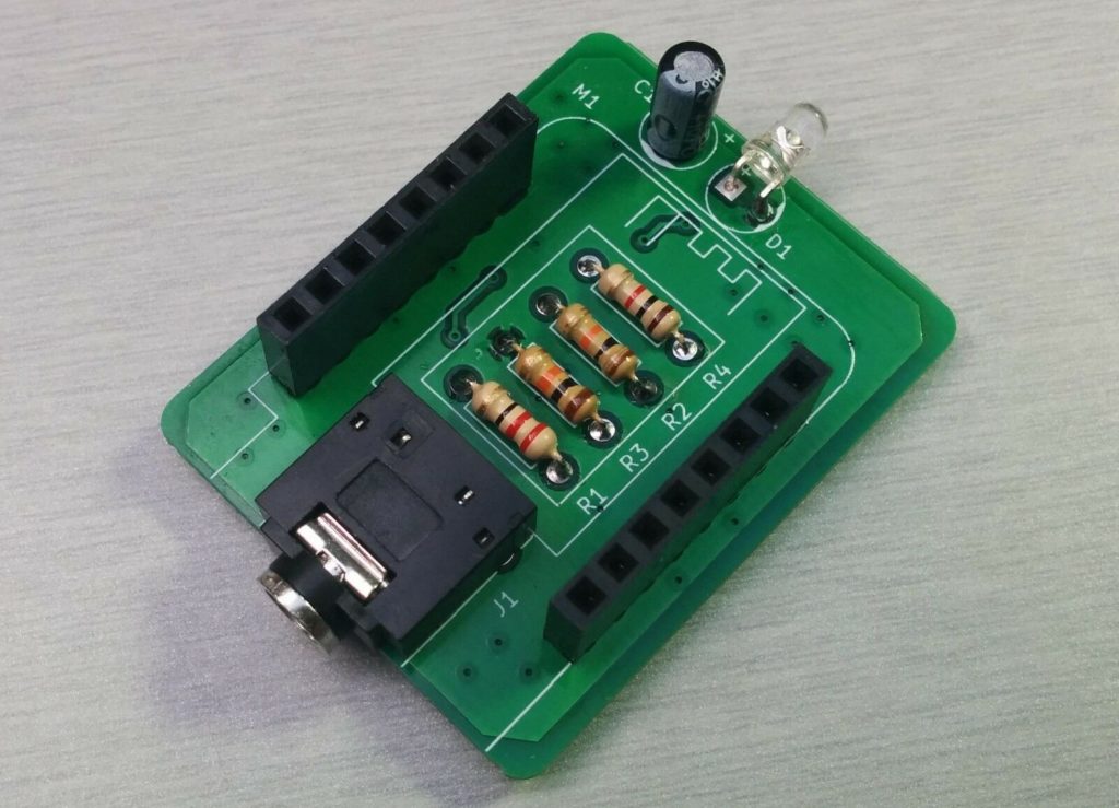
- Mottram Labs Module: Buy from eBay (eBay Partner Network Affiliate Link)
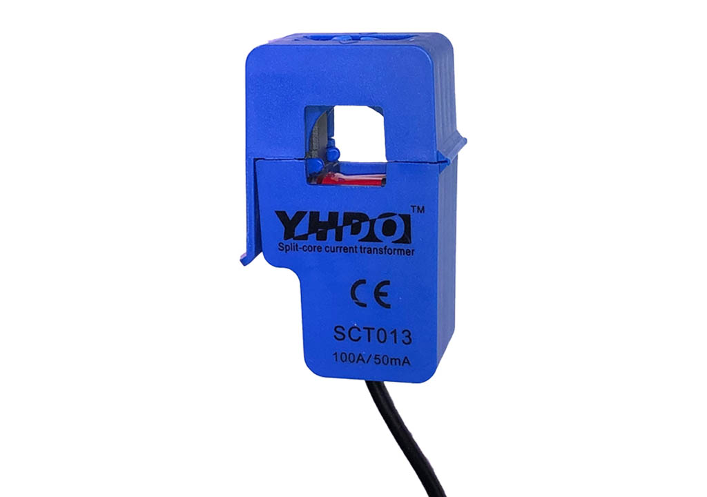
- CT Clamp (SCT-013-000): Buy from Amazon
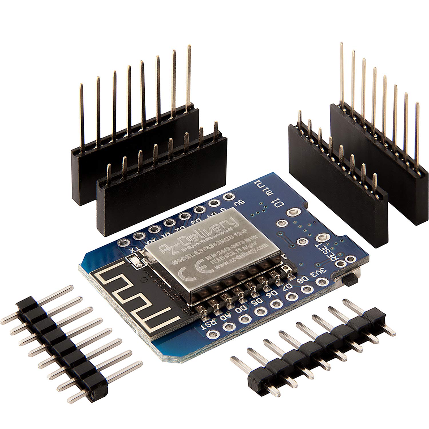
Firstly you need a microcontroller, and in this case you must get the D1 Mini, and you must make sure it either comes with soldered headers or that you can solder the headers on to it yourself. When you solder the headers on, you must make sure that the pins are pointing down and the main chip and antenna are on the top. And why is this so important? That’s because of the second component…
Mottram Labs have put together a brilliant bit of kit that hardly costs anything at all, honestly I don’t know how they can sell and ship this item for only £3.50! It does all the hard work of linking the CT clamp into the D1 Mini, and it’s been built to just connect perfectly together with the D1. I mean, to assemble the whole project, you just push the two items together! You can buy the module either from eBay or direct from their web site. They sell a lot of other cool modules too and are really worth checking out.
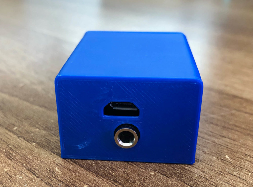
You also need a CT clamp - the Mottram Labs module has been designed to work with the SCT-013-000 clamp. I got mine from Amazon and it just plugs into the 3.5mm socket on the bottom of the module.
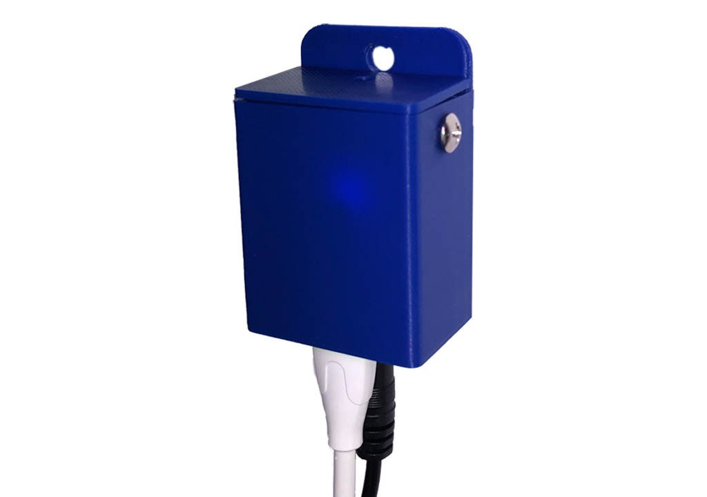
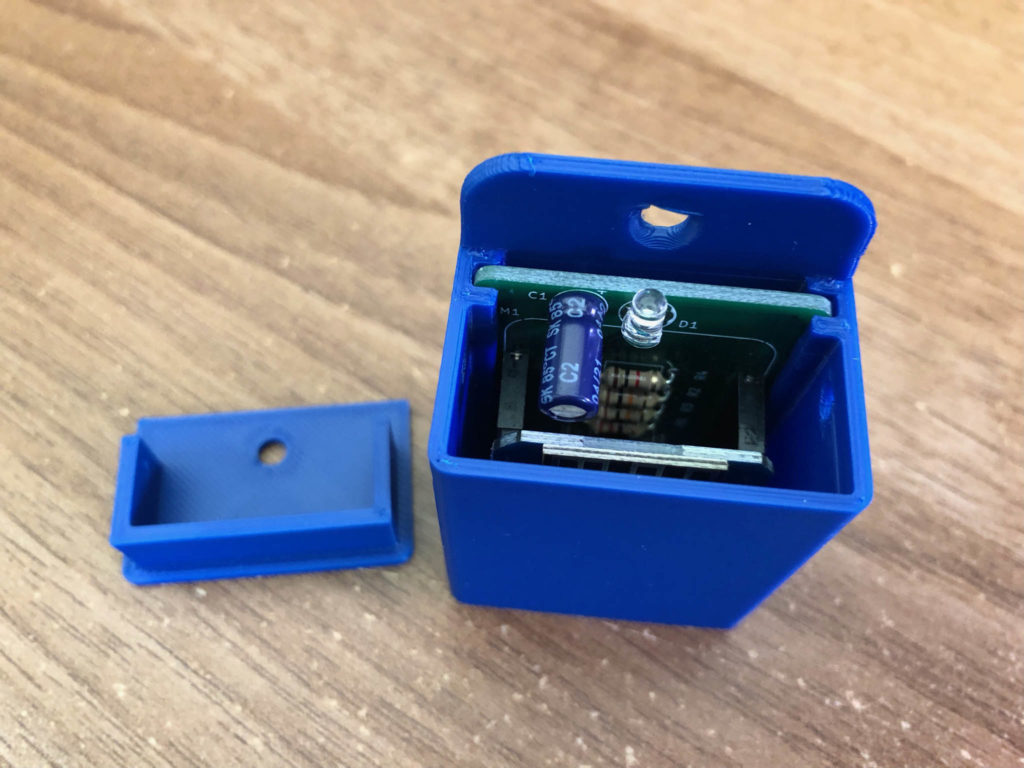
Oh yes, and finally you need to protect this bad-boy in a case. Mottram Labs even provide 3D files for cases on their web site for most of their projects so if you have a 3D printer you can download those print them out yourself. I’m not rich enough to have my own 3D printer, and I’ve never done any 3D printing before, but I decided to use an online 3D printing service to build a case for this sensor. I used the Craftcloud web site and was so excited when the parts arrived.
Right then, with the sensor assembled and all packaged up nicely, you need to program it. Now, there are a couple of catches here. CT Clamps measure the current running through a single power cable. If you cast your mind back to GCSE Physics, in order to calculate power (in watts) from current (in amps) then you need to know the voltage. In the UK, that is roughly 240v most of the time and you can hard code that value into the configuration if you like, but I have a better suggestion.

substitutions:
  device_name: power-sensor
  friendly_name: "Power Sensor"
  device_description: "CT-clamp power sensor"
  homeassistant_grid_voltage_entity: sensor.solaredge_ac_voltage_ab # Set this to an entity in Home Assistant that is monitoring your grid voltage


esphome:
  name: '${device_name}'
  comment: '${device_description}'

esp8266:
  board: d1_mini

# Enable logging
logger:

# Enable Home Assistant API
api:

wifi:
  ssid: !secret wifi_ssid
  password: !secret wifi_password

  # Enable fallback hotspot (captive portal) in case wifi connection fails
  ap:
    ssid: '${device_name}'
    password: !secret fallback_password

captive_portal:

ota:
  - platform: esphome

safe_mode:
  disabled: false
  reboot_timeout: 10min
  num_attempts: 5

output:
  - platform: esp8266_pwm
    id: power_led_output
    pin: D4

sensor:
  # The grid voltage entity from Home Assistant
  - platform: homeassistant
    name: "Grid Voltage Entity from Home Assistant"
    entity_id: '${homeassistant_grid_voltage_entity}'
    id: grid_voltage
    internal: true

  - platform: ct_clamp
    sensor: adc_sensor
    name: "Power Sensor Live Power"
    id: power_sensor_live_power
    update_interval: 5s
    accuracy_decimals: 0
    filters:
      - calibrate_linear:
        - 0.0008 -> 0.0
        - 0.036 -> 10.87
      - lambda: return x * id(grid_voltage).state;
    unit_of_measurement: "W"
    on_value:
      then:
        - script.execute: flash_led

  - platform: adc
    pin: A0
    id: adc_sensor
    internal: true


light:
  - platform: binary
    name: "Power Sensor LED"
    id: power_led
    output: power_led_output
    internal: true

script:
  - id: flash_led
    then:
      - light.turn_on:
          id: power_led
      - delay: 100ms
      - light.turn_off:
          id: power_led
My solar inverter is already measuring the AC voltage in my home, therefore my sensor configuration is importing that voltage sensor to use in the power calculation (set your entity on line 5). If however you don’t have anything measuring voltage, then you can just replace "id(grid_voltage).state" on line 59 with the number 240 and then delete the home assistant sensor section (lines 42 - 47). Your measurements won’t be quite so accurate, but it’ll all still work.
Octopus Energy using my referral link:
speaktothegeek.co.uk/energy

Existing customer? Find out how you can benefit too. T&Cs apply (only one switching offer per household)
Now we have the most complicated part. This sensor must be calibrated before it will give accurate results. The best way to calibrate it is to attach the clamp around a cable with a known current running through it. Perhaps this is one of your solar inverter cables, or the main meter tail in your meter box. Whichever one it is you must already know what the current is that’s running through that cable. There is a suggestion that you split the live and neutral cables out on an extension lead, attach the clamp around the live, and then plug in a 2kW heater. 2kW at 240v would be 9 amps. I am fortunate in that my solar inverter also reports how many amps it is exporting so by clamping around that cable I am able to see how much current is going through it. Once you have a wire with a known current on it you need to install your configuration on the D1 with the ‘calibrate-linear’ lines (56 - 58) commented out.
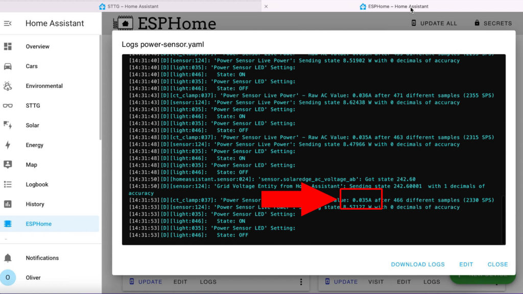
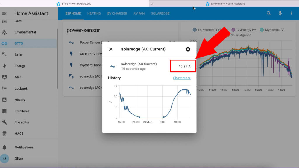
Once it’s installed you must keep your eye on the sensor logs (see screenshot above). You are looking to see how many amps it’s reporting. The idea is we must calibrate the sensor by telling it how much current was really going through the cable when it was reporting a specific value. So in this example the sensor is reporting 0.035 A but my inverter is reporting a real value of 10.87 A.
Back over in the configuration we un-comment the calibrate-linear section and make sure that line 58 says that at 0.035 A reported, it’s really 10.87 A (- 0.035 -> 10.87), and on line 57 at 0 A reported it should be 0 A (- 0 -> 0.0).
I found that I needed to calibrate the bottom end of the sensor slightly too because it was picking up some interference and reporting about 60 amps when nothing was connected, so my lower end calibration value is actually 0.008 -> 0.0.
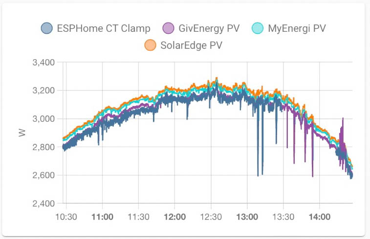
If we look at the values from the sensor in comparison to other monitoring solutions on the same cable, you can see it’s pretty close. My calibration probably needs adjusting slightly because I’m generally underreporting the value.
And that’s it. As I said, apart from the confusing part of calibration, it’s a ridiculously easy build process and very cheap to make. Going through the part list I paid:
- £3 for a D1 mini
- £3.50 for the Mottram Labs module
- £8.99 for the CT Clamp
- £8.77 for the 3D printed case
That’s a total of £24.26 for a smart Wifi connected CT clamp! I’m sure I could have paid less for the CT clamp if I’d been willing to wait for a couple of months for it to arrive from China.